You are using an out of date browser. It may not display this or other websites correctly.
You should upgrade or use an alternative browser.
You should upgrade or use an alternative browser.
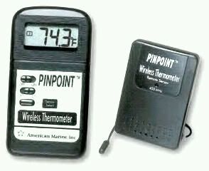
PINPOINT wireless temperature monitor
- Thread starter Js
- Start date


PINPOINT® Wirelsss Thermometer
User's Guide
American Marine is proud to introduce the PINPOINT® Wireless Thermometer. Utilizing a radio wave signal, the remote sensor(s) will measure the temperature at the waterproof probe tip and send the information to the PINPOINT® Temperature Display Monitor, which will display the temperature in Fº or Cº degrees. The PINPOINT® Wireless Thermometer can accept a maximum of 4 remote sensors thus expanding the monitoring capability to 4 separate locations to be displayed on the same PINPOINT® Temperature Display Monitor.
NOTE: The PINPOINT® Wireless Display Meter is NOT waterproof and must be operated on a dry surface. Liquid contact with any of the printed circuit boards will cause corrosion and void warranty.
Set-up For a Single Remote Sensor
1. Remove the battery compartment cover (Figure A) on the back of the PINPOINT® Temperature Display Meter and insert 2 AAA batteries in the proper positions. Replace the cover.
2. On the front of the PINPOINT® Temperature Display Meter, slide the top switch (Figure B) to the ON position then select to display either Fº or Cº with the middle switch (Figure C). When you see three minus signs flashing the meter is ready to receive a temperature signal.
3. On the back of the Remote Sensor carefully pry off the pop up stand (Figure E). Using the supplied screwdriver, remove the 4 philips head screws (Figure G) and lift off the battery cover. Insert 2 AAA batteries in the proper positions. Re-install the battery cover.
The Remote Sensor will automatically send a signal to the display meter within 1 minute. The PINPOINT® Temperature Display Meter will display the temperature of the #1 sensor. Remote sensors can transmit temperature signal as far as 100 feet (30 Meters) in optimum conditions. Transmitting distances through walls and other obstacles may reduce the effective range.
Using Additional Remote Sensors
After the successful installation of Remote Sensor #1, you may now install additional remote sensors up to a maximum of 4, if desired. You can place another sensor to monitor heat inside your lighting, on the ballast or even put a sensor outside. On the back of Remote Sensor #2 carefully pry off the pop up stand (Figure E). Using the supplied screwdriver, remove the 4 philips head screws (Figure G) and lift off the battery cover. Insert 2 AAA batteries in the proper positions. Re-install the battery cover. Within 1 minute Remote Sensor #2 will automatically send a signal to the display meter and will be recorded as the #2 remote sensor. This process can be repeated for up to 4 remote sensors.
Display a Single Temperature Sensor or Scroll Function will Display all the Temperature Sensors
By pressing the remote sensor button (Figure D) on the front of the PINPOINT® Display Meter, you may display any one of the remote sensors or have the display cycle through all available remote sensors.
Each time you press the Sensor Select button, the display will move to the next available remote sensor. Its corresponding number will be shown on the left side of the display. Once you reach the last available sensor, the Scroll Function Indicator (Fig. J) will be shown and the display meter will begin to cycle through all available sensors.
Important Points to Remember
* PINPOINT® Wireless Thermometer utilizes a remote sensor with a waterproof probe. This device has been fully tested and is in full compliance of FCC Part 15 Standards. FCC ID #Z9Z687000
* PINPOINT® Display Monitor is NOT waterproof and must be operated on a dry surface. The PINOINT Remote Sensor is weather resistant but must not be submerged under water. Liquid contact with any of the printed circuit boards will cause corrosion and void the warranty.
* The PINOINT Remote Sensor has a small red light on the front label that will blink only when the sensor is transmitting a temperature signal.
* When the PINPOINT® Display Meter receives a temperature signal from the Remote Sensor, the tower icon (Fig. H) will blink on the LCD.
* Check the function of the sensor(s) occasionally by applying heat or cold to the sensor probe tip to observe that communication is maintained between the remote sensor and the display meter.
* When the batteries are replaced in the PINPOINT® Display Monitor, or if the Display Monitor is turned off, the remote sensor(s) should be re-registered.
* When --- Fº appears on the display or if the temperature on the display is frozen; not reacting to a change in temperature, this indicates that the remote signal has been lost perhaps due to distance, etc. Re-register this sensor by pressing the sensor select button (Figure D) until the --- begins to flash. Then remove the batteries from the remote sensor and reinstall the batteries to reregister the sensor.
* Display Range: –50 Cº to +70 Cº, –58 Fº to +158 Fº Resolution: 0.1 Cº, 0.2 Fº
Replace batteries in the PINPOINT® Temperature Display Meter when the LCD display appears dim, approximately 18 months. Replace batteries in the Remote Sensor when the battery icon on the LCD display (Fig. I) appears empty, approximately 18 months.
* FCC Declaration of Conformity
This device complies with Part 15 of the FCC Rules. Operation is subject to the following two conditions:
1. This device may not cause harmful interference
2. This device must accept any interference received, including interference that may cause undesired operation.
